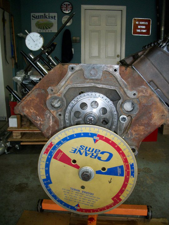
2. A stable pointer that can be conveniently mounted to the
engine.
3. A dial indicator with at least a half inch of travel in
.001" increments. A rigid stand that mounts to the engine or
with a magnetic base to hold the dial indicator will also be
required.
4. A positive stop device to locate T.D.C.
Determining exactly where Top Dead Center is can be
tricky. The problem in finding the true T.D.C. of the piston's
travel is that the piston dwells at T.D.C. for several degrees of
crankshaft rotation. You must use a device to stop the piston in
the same position on either side of T.D.C. and take readings from
the degree wheel.
You will then split the difference in these readings and move the
pointer this amount, making it the true T.D.C. point. Begin the
procedure by first mounting the degree wheel on the end of the
crankshaft securely, and rotating the engine to approximately
T.D.C. Mount the pointer and line it up at zero on the degree
wheel. Now rotate the engine to move the piston down into the
cylinder. Install your positive stop device into the spark plug
hole and extend the bolt. Now hand turn the engine (do not use
the starter motor or you will put a hole through the piston),
rotating until the piston comes up and stops against the bolt.
Look at the degree wheel and write down the number of degrees
shown by the pointer.
Hand turn the engine in the opposite direction
until the piston comes up and stops on the bolt again. Go back to
the degree wheel and write down the degrees it now reads. Add
these two readings together and divide the answer by two. Now
either move your pointer by this many degrees, or carefully loosen
the degree wheel (without disturbing the position of the
crankshaft) and move the wheel this required amount. Retighten the
bolts, and rotate the engine again making sure that the readings
on each side of T.D.C. are equal degrees away from zero. If they
are, the zero on the degree wheel will now be the true T.D.C.
point. Remove the positive stop device from the spark plug hole,
as this procedure is complete.
The dial indicator and stand must be
attached securely to the engine. Any deflection could cause an
error in your readings. Using the number one cylinder as a
starting point, hand rotate the engine in a normal direction
(clockwise, when standing in front of the engine) until the
intake valve is at the highest point and zero the dial.
Hand rotate the engine back till it
passes the .050� mark then bring it forward till it is at
the .050� mark and stop. Take a reading on the wheel.
As you continue to rotate the engine, the
reading on the dial indicator will rise up to the maximum lobe
lift. The lifter is now on the top of the lobe, Continue the
rotation and the lifter will start down the closing side of
the lobe.
Carefully watch the dial indicator as the
numbers descend. When the indicator descends back to the
.050" reading, stop, take a reading from the degree wheel
and write it down.
You now have the two important readings
from the degree wheel, both taken when the dial indicator read
.050". Add the two numbers together and divide by
two. This will give you your lobe center.
The camshaft specification card provides much information, but
the numbers you are most interested in for the degreeing of
the cam are the lobe centers.
You can follow exactly the same procedure
on the exhaust lobe to determine its center and compare these
readings to those on the specification card. If you also check
the exhaust lobe you will have two points of reference (intake
center, and the exhaust center) to go by. Remember, if you are
plus or minus one degree of these readings, your cam is in the
correct location and will be synchronized to the crankshaft's
rotation.
 Tech Tips